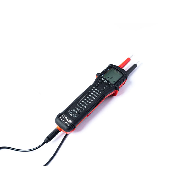
A continuity tester is a relatively simple device used to verify that a complete electrical path exists in a circuit. The continuity tester works by applying a small voltage to one end of a circuit and it will indicate whether that current flow is received at the other end of the circuit. If this is the case then the circuit is closed and there is a clear electrical path, ie. you have continuity and there are no obstructions or breaks in the circuit.
In electrical testing a circuit can mean a lightbulb, a length of wire, or a fuse, and it can also mean the circuit in switches, electrical connections and conductors.
Understanding the continuity tester
It is possible to measure continuity using a multimeter, and this is a popular instrument for electrical testers who have a wide range of different testing responsibilities, but a continuity tester is a single-purpose instrument which is very easy to use.
The continuity tester consists of two test leads which are attached to the main body of the instrument. The test leads will each have a pointed end, which may be protected from damage by a protective and removable cap. The body of the instrument will have an indicator light. When carrying out the test of any circuit you are applying a small voltage to one end of the circuit by touching it with one test lead, and measuring at the other end of the circuit with the other test lead, that voltage is being received and there is continuity in the circuit.
Checking electrical continuity in different electrical circuits
An essential safety process that you must complete before carrying out any continuity testing is to de-energise and isolate the circuit you are testing. So before removing any device from its circuit and before accessing any internal wiring in a device, you must ensure that all power is off and removed from the circuit and that power is isolated BY USING THE CORRECT ELECTRICAL SAFE ISOLATION PROCESS & LOCKING OFF THE CIRCUIT BREAKER OR FUSE WITH THE APPROPRIATE LOCK & TAG KIT.
Continuity testing of a fuse
- Remove the fuse from its de-energised circuit, either by pulling the fuse out or by removing the lead from one side of the fuse
- With the fuse separated from its circuit touch the two test leads to the contact on either side of the fuse
- If the fuse has continuity then the indicator light on the continuity tester will light up or it will buzz
- If the fuse does not have continuity there will be no indication
Continuity testing of an incandescent lightbulb
- Remove/unscrew the lightbulb from the de-energised light fitting
- Touch one test lead onto the base of the metal screw portion of the lightbulb, and touch the other test lead on the side of the screw portion. This should form a circuit.
- If there is continuity in the lightbulb circuit the tester will indicate this
- If there is no continuity in the lightbulb there will be no indication
Continuity testing of wiring
- This test will check for continuity in a length of wire, but the test is limited to the physical reach of the test leads, so it may be required to test multiple lengths of the wiring depending on the nature of your tests
- Touch one test lead on the starting end of the de-energised wire length
- Touch the other test lead on the end point of the wire length
- If there are no breaks in the wiring you will have continuity and the tester will indicate this
If there is a break in the wiring there will be no continuity and no indication.
Please note that this section is for information purposes only. Anyone using equipment referred to in this section must be suitably qualified and/or experienced within the respective field. If in doubt before use, please consult a qualified electrician or engineer & thoroughly read all instruction booklets.